

ASSEMBLING THE ARDUINO
STEP 4 — CONNECT THE GPS BOARD
The next component we will begin to assemble is the GPS Breakout Board. This board has quite a few pins (nine to be exact). You can learn more about what these pins do in this tutorial.
Once again, we will only be using four of these pins in this activity:
3.3V — 3.3 V power output from GPS (not used here)EN — manually turn GPS on/off (not used here)VBAT — external battery input (not used here)FIX — satellite fix output (not used here)
TX — output data from the GPS to Arduino
RX — input data to the GPS from Arduino
GND — grounds the GPS and completes the circuit
VIN — input power to the GPS from Arduino (needs 5 V)PPS — pulse per second output (not used here)
The Breadboard
First, attach the GPS Breakout Board somewhere on the breadboard. Technically, you don’t need to use the breadboard at all in this activity. However, the GPS Breakout Board needs to be firmly secured during flight so that it doesn’t bounce around and disconnect from the GPS Antenna. The breadboard provides a solid platform upon which the GPS Breakout Board can be mounted.
Breadboards are tools we use to help us organize our electronics. A breadboard has lots of “terminals”, or little holes, which are connected to each other in certain ways. In the image above, all the green lines show which terminals on the breadboard connect with each other via a metal strip underneath. In other words, the green lines are basically extra wires. You can check out this brief breadboard tutorial to learn more if you wish.
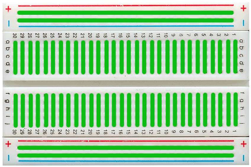
Electrically Connected Rows in a Breadboard (green lines)
Wiring the Pins
With the GPS Breakout Board mounted on the breadboard, you can now connect the GPS board to the Arduino by inserting the wires into breadboard terminals that lie along the same “green lines” as the GPS board pins.
As with the Radiation Sensor, connect the VIN and GND pins on the GPS board to the appropriate pinouts on the Arduino (once again, remember that the GPS board needs 5 V). Since the GPS board is mounted right next to the Arduino, you can use shorter wires this time. Connect the RX pin to the digital 10 pinout on the Arduino. The TX pin connects to the Arduino’s digital 11 pinout.
After connecting the GPS board, move on to Step 5.