

ASSEMBLING THE ARDUINO
STEP 5 — CONNECT THE GPS ANTENNA
Although the GPS Breakout Board does have a built-in patch antenna, it’s view of the sky will be entirely obstructed by the walls of the payload box during flight. This may cause the GPS signal quality to be degraded. In order to receive high-quality signals from the GPS satellites, we need to connect the GPS board to an external GPS Antenna that will sit outside of the payload box with an unobstructed view of the sky.
Unfortunately, most GPS antennas (including the one we’re using) have an “SMA connector”. The GPS Breakout Board, on the other hand, has a “uFL connector” instead. To connect these two components, we will use the SMA-to-UFL adapter cable. Using this adapter, the two SMA connections screw together easily while the two uFL connectors simply snap together. Check out this tutorial to learn more.

Location of uFL connection between antenna and GPS board
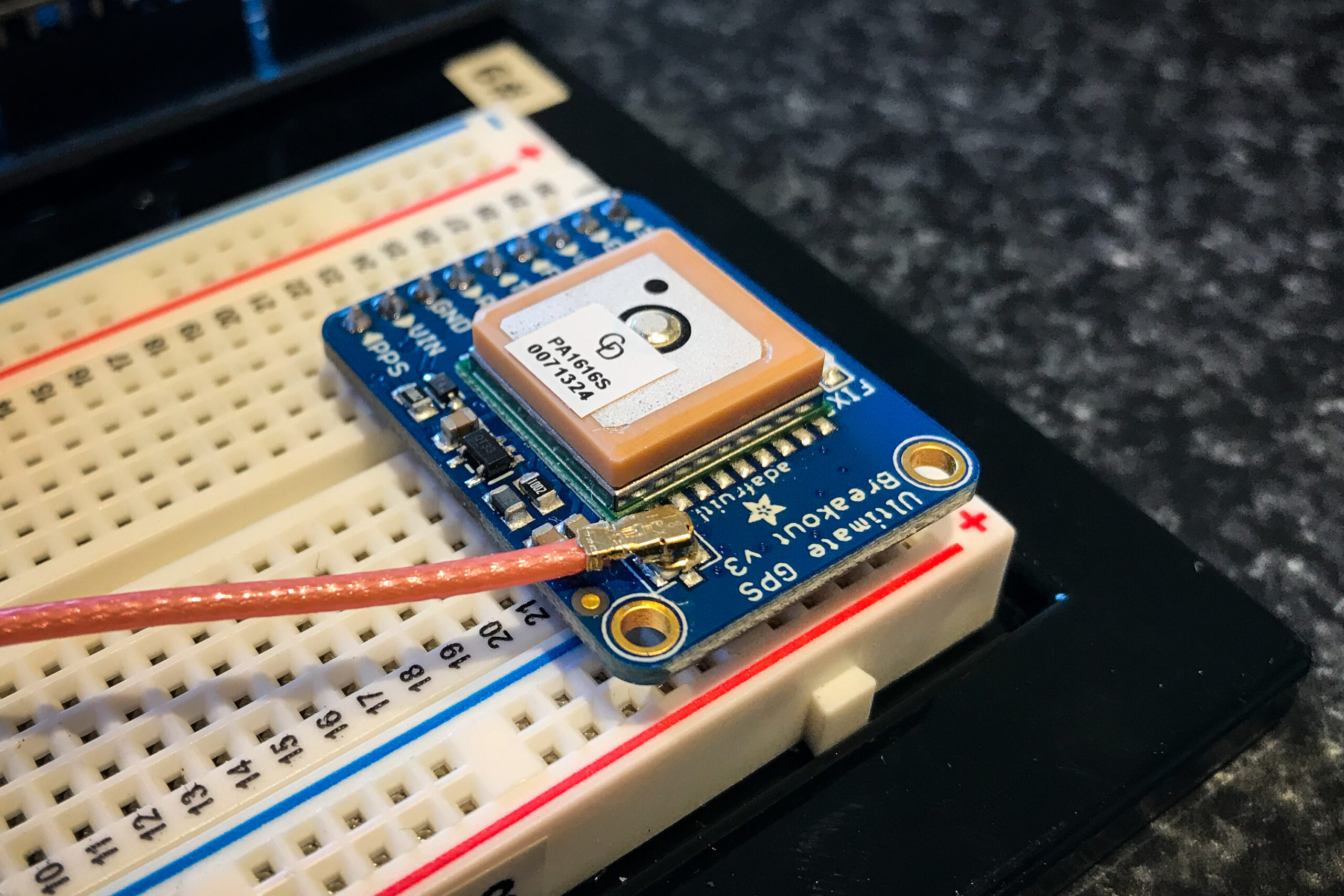
The uFL connectors are attached
Please note that it doesn’t take too much force to separate the uFL connectors, so please be gentle. Prior to the balloon flight, we will use hot glue to strengthen their connection.
With the GPS Antenna now connected to the GPS Breakout Board, the Engineer in your group will need to figure out how to mount the antenna facing up on the outside of the payload box.